
Splat Wiring Diagram
TECHS AND DIY'ERS, PLEASE NOTE:
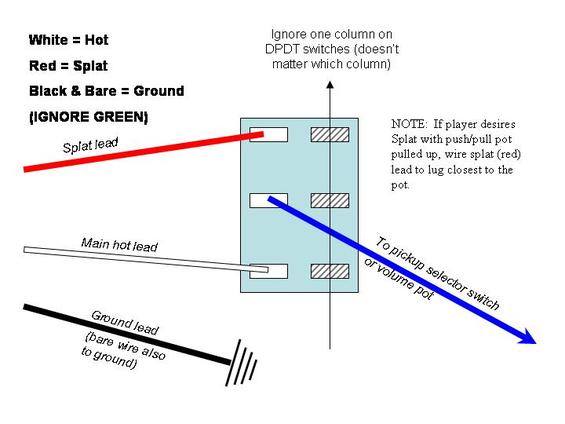
Please follow the above diagram for installation. Do NOT use the ground-out method for cutting out the unused part of the pickup. The Splat pickup is designed for the choose-between-two-hot-leads method where the unused portion is just cut out of the circuit, not grounded out.
Grounding the unused portion may reduce noise somewhat but unfortunately it also reduces tone by shunting some of the high frequencies to ground via eddy currents, much like a bad humbucker cover, because the unused portion entirely covers the portion still in use.
You may also end up grounding out the wrong side of the Splat. For example, on a 7.5k pickup with a 5.8k Splat, you may ground out the 5.8k portion and thus get only the 1.7k portion when you throw the switch. In this example, the 1.7k resides between the red and white leads, the 5.8k is between red and black. Thus grounding both black and red when the switch is thrown means you will get only 1.7k.
